Vickers Hardness Test
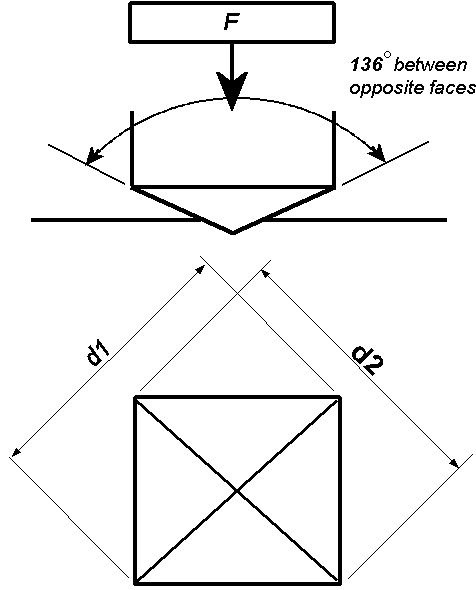
The Vickers hardness test method consists of indenting the test
material with a diamond indenter, in the form of a right pyramid with a
square base and an angle of 136 degrees between opposite faces
subjected to a load of 1 to 100 kgf. The full load is normally applied
for 10 to 15 seconds. The two diagonals of the indentation left in the
surface of the material after removal of the load are measured using a
microscope and their average calculated. The area of the sloping
surface of the indentation is calculated. The Vickers hardness is the
quotient obtained by dividing the kgf load by the square mm area of
indentation.

F= Load in kgf
d = Arithmetic mean of the two diagonals, d1 and d2in mm
HV = Vickers hardness

When the mean diagonal of the indentation has been determined the
Vickers hardness may be calculated from the formula, but is more
convenient to use conversion tables. The Vickers hardness should be
reported like 800 HV/10, which means a Vickers hardness of 800, was
obtained using a 10 kgf force. Several different loading settings give
practically identical hardness numbers on uniform material, which is
much better than the arbitrary changing of scale with the other
hardness testing methods. The advantages of the Vickers hardness test
are that extremely accurate readings can be taken, and just one type of
indenter is used for all types of metals and surface treatments.
Although thoroughly adaptable and very precise for testing the softest
and hardest of materials, under varying loads, the Vickers machine is a
floor standing unit that is more expensive than the Brinell or Rockwell
machines.
Vickers Hardness Number Calculator
There is now a trend towards reporting Vickers hardness in SI units
(MPa or GPa) particularly in academic papers. Unfortunately, this can
cause confusion. Vickers hardness (e.g. HV/30) value should normally be
expressed as a number only (without the units kgf/mm2).
Rigorous application of SI is a problem. Most Vickers hardness testing
machines use forces of 1, 2, 5, 10, 30, 50 and 100 kgf and tables for
calculating HV. SI would involve reporting force in newtons (compare
700 HV/30 to HV/294 N = 6.87 GPa) which is practically meaningless and
messy to engineers and technicians. To convert a Vickers hardness
number the force applied needs converting from kgf to newtons and the
area needs converting form mm2 to m2 to give
results in pascals using the formula above.
To convert HV to MPa multiply by 9.807
To convert HV to GPa multiply by 0.009807
Or use conversion calculator
Links To:
Hardness Testing
Rockwell Hardness Test
Rockwell Superficial Hardness Test
Brinell Hardness Test
Vickers Hardness Test
Microhardness Test
Mohs Hardness Test
Scleroscope and other hardness testing methods
Hardness Conversion Tables and Charts:
Hardness Conversion Table(colour version - may take time to load)
Hardness Conversion Table(non-colour version)
Hardness Conversion Chart (1)
Hardness Conversion Chart (2)
Chart of Brinell, Vickers and Ultimate Tensile Strength Equivalents (1)
Chart of Brinell, Vickers andUltimate Tensile Strength Equivalents (2)
Hardness Conversion Table related to Rockwell C Hardness Scale (hard materials) (colour)
Hardness Conversion Table related to Rockwell C Hardness Scale (hard materials) (non-colour)
Hardness Conversion Chart related to Rockwell C Hardness Scales (hard materials)
Estimated Hardness Equivalent Chart related to Rockwell C and Vickers (hard materials)
Hardness Conversion Table related to Rockwell B Hardness Scale (soft metals) (colour)
Hardness Conversion Table related to Rockwell B Hardness Scale (soft metals) (non-colour)
Hardness Conversion Chart related to Rockwell B Hardness Scale (soft metals)
Table of Minimum Test Piece Thickness for Rockwell Hardness Testing using Ball Indenters
Table of Minimum Test Piece Thickness for Rockwell Hardness Testing using Diamond Indenters
HV, MPa and GPa Conversion Calculator


Telephone: +44 (0)1252 405186
Email: tsc@gordonengland.co.uk
Site Links
Introducing
Nature of Thermal Spray Coatings
Surface Engineering in a Nutshell
Surface Engineering Forum
Thermal Spray Gun Repair Service
Plasma Consumable Parts
Thermal Spray Powder Supplies
Applications:
Thermal Spray Coatings on Carbon and Glass Fibre Reinforced Polymers
HVOF Coating of Paper Making Roll
Abradable Coatings
Photomicrographs
Thermal Spray Processes:
Combustion Wire Thermal Spray Process
Combustion Powder Thermal Spray Process
Arc Wire Thermal Spray Process
Plasma Thermal Spray Process
HVOF Thermal Spray Process
HVAF Thermal Spray Process
Detonation Thermal Spray Process
Plasma Flame Theory
Cold Spray Coating Process
Wear and Use of Thermal Spray Coatings
Corrosion and Use of Thermal Spray Coatings
Glossary of Thermal Spray and Surface Engineering Terms
Image Directory for Thermal Spray Coatings
Plasma Gas Flow Information
Plasma Gas Flow Correction Calculator
Contact Form
Links to other interesting sites related to thermal spray and surface engineering
Reciprocal Links
Periodic Table of the Elements
SI Units
Calculators for Conversion between Units of Measurement
Hardness Testing
Surface Engineering Message Board Archive
Surface Engineering Message Board Archive Index
Photography Gallery
Photography Gallery3
© Copyright Gordon England


